


Victron Energy
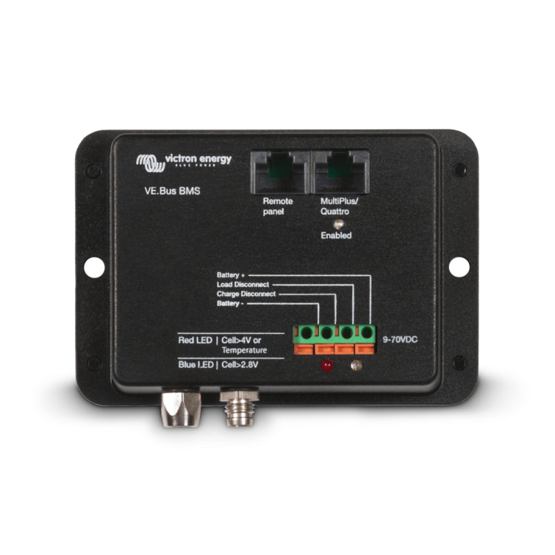
Victron Battery Management System VE.Bus BMS
Battery Management System VE.Bus BMS by Victron
Protects each individual cell of a Lithium Iron Phosphate (LiFePO4 or LFP) battery
Each individual cell of a LiFePO4 battery must be protected against overvoltage, undervoltage, and overtemperature.
Victron LiFePO4 batteries have a built-in cell balancing, temperature, and voltage control (hence the acronym: BTV). They are connected to the VE.Bus BMS via two M8 circular connector cable sets.
The BTVs of multiple batteries can be daisy-chained. Up to ten batteries can be connected in parallel and up to four batteries in series (BTVs are simply daisy-chained), allowing a 48V battery bank of up to 3000 Ah to be assembled. For more details, please refer to the technical documentation for Victron LiFePO4 batteries.
Tasks of the BMS:
- Switching off or disconnecting loads in case of imminent undervoltage
- Reducing the charging current in case of imminent cell overvoltage or overtemperature (only for VE.Bus products)
- Switching off or disconnecting battery chargers in case of imminent cell overvoltage or overtemperature.
Overview of a Battery System
You can customize your battery system individually.
Three components are used to control the energy flows:
-
VE.Bus BMS
is the central control unit. The data cables of the batteries are connected so that the BMS can forward the read-out information for the appropriate switching commands. Furthermore, there are numerous other communication ports, which can be used to control, for example, MultiPlus inverters or high-current relays. -
Cyrix Li Load
This device is connected between the load and the power supply (the batteries). If the battery is running low (undervoltage alarm), the consumers are disconnected from the battery. -
Cyrix Li Charge
The Charge Li device is located between the batteries and chargers (such as the solar system or, for example, the alternator). If the energy source provides too much power (overvoltage message), the charger is disconnected.
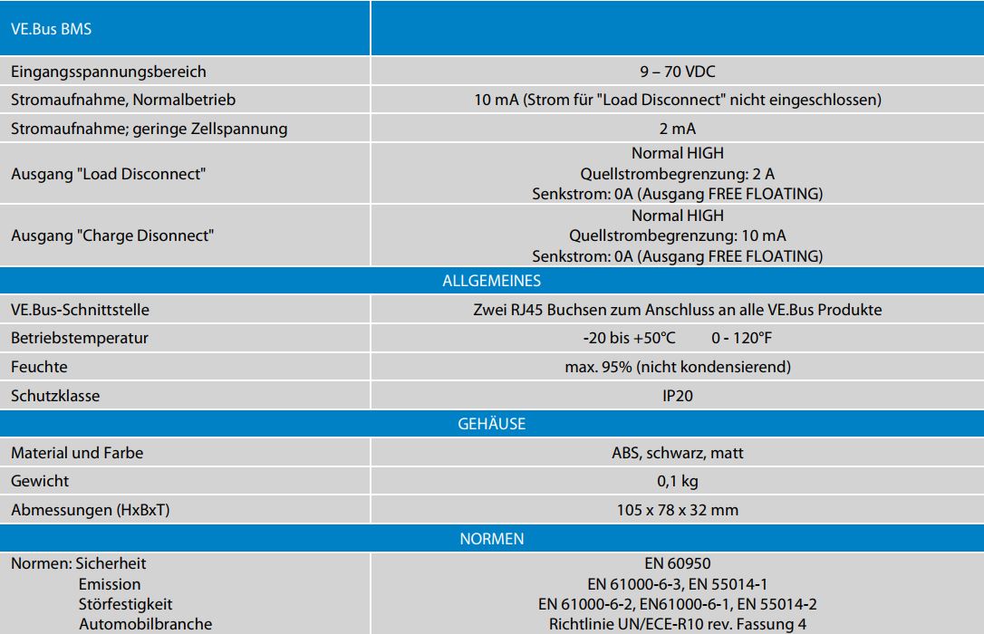
Technical Data
We continuously evaluate this product according to our MI-Eco-Score criteria.
We continuously evaluate this product according to our MI-Eco-Score criteria.
We continuously evaluate this product according to our MI-Eco-Score criteria.
We continuously evaluate this product according to our MI-Eco-Score criteria.
We continuously evaluate this product according to our MI-Eco-Score criteria.
We continuously evaluate this product according to our MI-Eco-Score criteria.
We continuously evaluate this product according to our MI-Eco-Score criteria.
We continuously evaluate this product according to our MI-Eco-Score criteria.
We continuously evaluate this product according to our MI-Eco-Score criteria.
We continuously evaluate this product according to our MI-Eco-Score criteria.
We continuously evaluate this product according to our MI-Eco-Score criteria.
We continuously evaluate this product according to our MI-Eco-Score criteria.
We continuously evaluate this product according to our MI-Eco-Score criteria.
We continuously evaluate this product according to our MI-Eco-Score criteria.
We continuously evaluate this product according to our MI-Eco-Score criteria.
We continuously evaluate this product according to our MI-Eco-Score criteria.
We continuously evaluate this product according to our MI-Eco-Score criteria.
We continuously evaluate this product according to our MI-Eco-Score criteria.
We continuously evaluate this product according to our MI-Eco-Score criteria.
We continuously evaluate this product according to our MI-Eco-Score criteria.
We continuously evaluate this product according to our MI-Eco-Score criteria.
We continuously evaluate this product according to our MI-Eco-Score criteria.
We continuously evaluate this product according to our MI-Eco-Score criteria.
We continuously evaluate this product according to our MI-Eco-Score criteria.