


Victron Energy
Victron Battery Management System smallBMS with pre-alarm
A simple and cost-effective alternative to the VE.Bus BMS
The smallBMS can replace the VE.Bus BMS in several applications. However, it is not suitable for use with VE.Bus MultiPlus and Quattro inverters/chargers: there is no VE.Bus interface. The smallBMS is designed for use with Victron Smart LiFePo4 batteries with M8 circular connectors.
The smallBMS has two outputs, similar to the VE.Bus BMS.
Load isolation output
The load output is normally high and becomes free floating when the cell is under voltage (default 2.8 V/cell, adjustable
on the battery between 2.6 V and 2.8 V per cell). Maximum current: 1 A. The "Load" output is not short-circuit protected.
The "Load" output can be used to control the following functions:
A high current relay or contactor
The remote on/off input of BatteryProtect, inverter or DC-DC converter or other loads.
(A non-inverting or inverting cable for on/off switching may be necessary, please refer to the manual)
Charging disconnect output
The charger output is normally high and will float in the event of an impending overvoltage or overtemperature of the cell.
Maximum current: 10 mA.
The “Charger” output is not suitable for driving an inductive load such as a relay coil.
The Charger output can be used to control the following devices:
• Remote controlled on/off switch of a charger.
• Cyrix Li-charging relay.
• Cyrix-Li-ct battery coupler.
Pre-alarm output
The pre-alarm output is normally free floating and is set high when the cell voltage is approaching low (standard 3.1 V/cell, adjustable on
of the battery between 2.85 V and 3.15 V per cell). Maximum current: 1 A (not short-circuit proof).
The minimum delay between pre-alarm and load disconnection is 30 seconds.
Output “Charge disconnect”
The Charger output is normally HIGH and becomes free floating when a cell overvoltage or -
Overtemperature is imminent. Maximum current: 10 mA.
The "Charger" output is not suitable for driving an inductive load such as a relay coil.
The Charger output can be used to control the following devices:
- Remote controlled on/off switch of a charger
- Cyrix Li-ion charging relay.
- Cyrix-Li-ct battery coupler.
System on/off input
The system on/off input controls both outputs. In the off state, both outputs are free floating, so that loads and
Chargers are switched off.
The “System on/off” input has two connectors: Remote L and Remote H.
A remote-controlled on/off switch or a relay contact can be connected between L and H.
Alternatively, terminal H can be connected to a positive battery terminal or L to a negative battery terminal.
Protects 12 V, 24 V and 48 V systems
Operating voltage range: 8 to 70 V DC
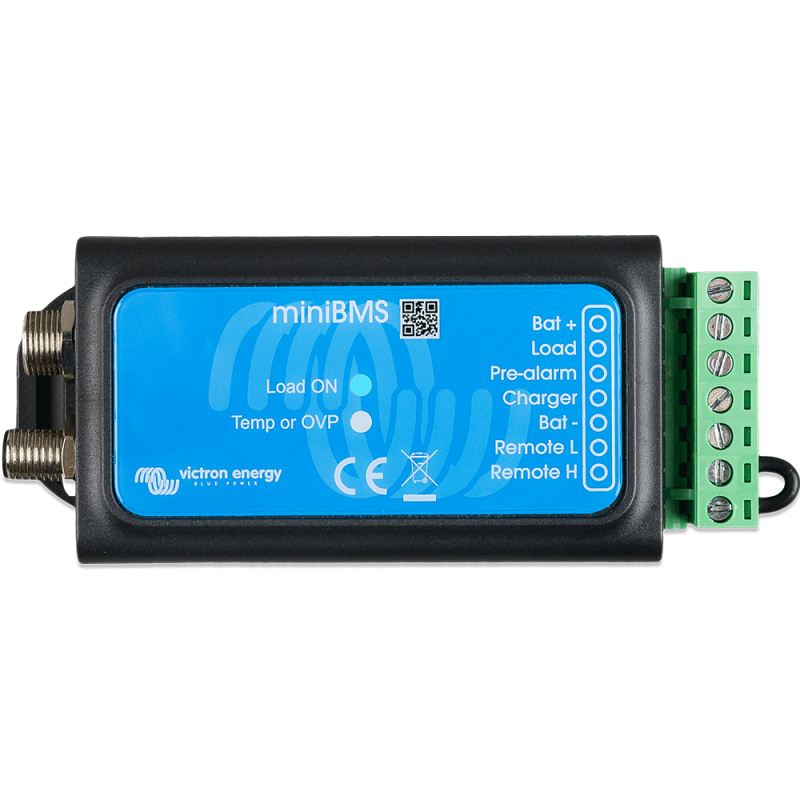
LED displays
- Load ON (blue): Load output high (cell voltage > 2.8 V, adjustable at the battery).
- Temp or OVP (red): The charger output is floating (due to cell overtemperature (>50°C), cell undertemperature (<5
°C) or cell overvoltage).